📔
Today Joonas Learned
  • Home
  • About Me
  • Chrome Extension
    • CSS injection
  • Design Pattern
    • SOLID 원칙
      • 1. SRP
      • 2. OCP
      • 3. LSP
      • 4. ISP
      • 5. DIP
    • 생성 패턴
      • Singleton Pattern
      • Abstract Factory Pattern
      • Factory Method Pattern
    • 구조 패턴
      • Adapter Pattern
      • Bridge Pattern
      • Composite Pattern
      • Decorator Pattern
      • Facade Pattern
      • Proxy Pattern
    • 행위 패턴
      • Command Pattern
      • Observer Pattern
      • State Pattern
      • Strategy Pattern
      • Template Method Pattern
  • Graphics
    • OpenGL ES
      • 파이프라인
      • 삼각형 그리기
      • 삼각형 움직이기
      • 다각형 그리기
      • 정사면체 그리기
      • [WIP] 마인크래프트 블럭 만들기
      • [WIP] Lighting, Normal Mapping
  • Internet
    • iOS/Safari
  • Javascript
    • async, defer 속성
    • 나머지 매개변수 (Rest parameter)
    • 화살표 함수 표현 (arrow function expression)
    • Template Literals
    • TDZ (Temporal Dead Zone)
    • Spread syntax (...)
  • Network
    • OSI 7 계층 모델
  • Uncategorized
    • 2021/12/07
    • 2020/09/03
    • 2020/09/04
    • 2020/08/22
  • git/VCS
    • Merge 커밋 메시지 수정
Powered by GitBook
On this page
  • Code
  • Links

Was this helpful?

  1. Graphics
  2. OpenGL ES

삼각형 그리기

Android에서 OpenGL ES 2.0으로 삼각형을 정의하고, SurfaceView에 그려본다.

Previous파이프라인Next삼각형 움직이기

Last updated 4 years ago

Was this helpful?

우선 OpenGL ES는 3차원 공간에서 좌표로 객체를 그린다.

객체는 각 점(vertex)들을 따라가면서 만들어지는 면(fragment)를 그리는 방식이고, 좌표는 반시계 방향 순서로 정의한다.

OpenGL ES에서는 (0, 0, 0)이 프레임의 중앙, (1, 1, 0)이 프레임의 오른쪽 위이다.
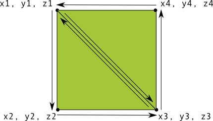
[그림 1] 두 개의 삼각형으로 사각형 그리기

공식 예제 코드에서는 적당한 삼각형이지만, 아래 코드는 정삼각형으로 수정하였다.

public class Triangle {

    // number of coordinates per vertex in this array
    static final int COORDS_PER_VERTEX = 3;
    static float triangleCoords[] = {
            // in counterclockwise order:
            0.0f, 0.577350269f, 0.0f,     // top
            -0.5f, -0.288675134f, 0.0f,   // bottom left
            0.5f, -0.288675134f, 0.0f     // bottom right
    };

    private final int vertexCount = triangleCoords.length / COORDS_PER_VERTEX;
    private final int vertexStride = COORDS_PER_VERTEX * 4; // 4 bytes per vertex
    
    float color[] = { 0.63671875f, 0.76953125f, 0.22265625f, 1.0f };
    
    public Triangle() {
        // initialize vertex byte buffer for shape coordinates
        ByteBuffer bb = ByteBuffer.allocateDirect(
            // (number of coordinate values * 4 bytes per float)
            triangleCoords.length * 4);
        
        // use the device hardware's native byte order
        bb.order(ByteOrder.nativeOrder());
        vertexBuffer = bb.asFloatBuffer();
        vertexBuffer.put(triangleCoords);
        vertexBuffer.position(0);
    }
}

도형을 그리는 데 필요한 것:

  • Vertex Shader - 도형의 꼭짓점을 렌더링하는 OpenGL ES 그래픽 코드

  • Fragment Shader - 색상 또는 질감으로 도형의 면을 렌더링하는 OpenGL ES 코드

  • Program - 하나 이상의 도형을 그리는 데 사용할 셰이더가 포함된 OpenGL ES 객체

Vertex Shader 와 Fragment Shader 는 코드이다. 따라서 컴파일 할 GLSL(OpenGL Shading Language) 코드로 작성된다.

public class Triangle {

    private final String vertexShaderCode =
        "attribute vec4 vPosition;" +
        "void main() {" +
        "  gl_Position = vPosition;" +
        "}";

    private final String fragmentShaderCode =
        "precision mediump float;" +
        "uniform vec4 vColor;" +
        "void main() {" +
        "  gl_FragColor = vColor;" +
        "}";

    ...
}

각 도형들이 Program 을 가지고 있고, 렌더러(Renderer)가 나중에 이 프로그램을 렌더링에 추가하여 객체를을 그릴 것이다.

SurfaceView에서 Renderer를 통하여 OpenGL ES 객체를 그리는 것이다.

두 셰이더(Shader)와 프로그램(Program), 그리고 렌더러(Renderer)까지 예제를 잘 따라했다면 삼각형이 그려지는 것을 볼 수 있다.
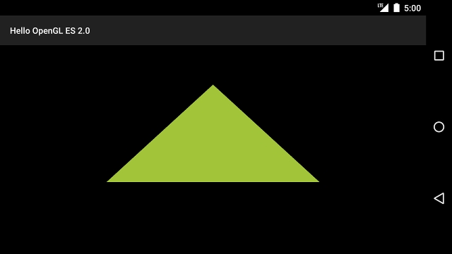
그런데 삼각형이 찌그러져 있을 것이다. 분명 정삼각형을 정의했는데!

그 이유는 프로젝션(Projection)과 카메라 뷰(Camera View)가 없어서 그렇다.

[그림 2]에서 우리가 그래픽을 그리는 GLSurfaceView는 [그림 3]의 오른쪽처럼 뷰 포트의 크기가 변한다.

이것을 GLSurfaceView의 너비와 높이를 보고 다시 좌표를 조정해야하는데, 투영(Projection)시키기 위해서 가상의 카메라 위치를 잡아야한다.

public class MyGLRenderer implements GLSurfaceView.Renderer {

    // vPMatrix is an abbreviation for "Model View Projection Matrix"
    private final float[] mMVPMatrix = new float[16];
    private final float[] mProjectionMatrix = new float[16];
    private final float[] mViewMatrix = new float[16];

    @Override
    public void onSurfaceChanged(GL10 unused, int width, int height) {
        // Adjust the viewport based on geometry changes
        GLES20.glViewport(0, 0, width, height);
        float ratio = (float) width / height;

        // this projection matrix is applied to object coordinates
        // in the onDrawFrame() method
        Matrix.frustumM(mProjectionMatrix, 0, -ratio, ratio, -1, 1, 3, 7);
    }
    
    ...
}

[그림 3]을 보면 좌표계는 [-1.0, 1.0] 사이의 값으로 표현된다. 찌그러진 것을 복구하기 위해서 좌표의 아래(bottom)와 위(top)를 -1과 1로 했을 때, 왼쪽(left)과 오른쪽(right)의 비율만 조정하는 것이다.

위 그림에서 Near와 Far가 아주 가까워 착 붙어있는 뷰 포트에 투영시킨다고 생각하면 되겠다.

Matrix.frustumM() 함수는 그렇게 비율을 조정하는 행렬(Matrix)을 첫 번째 인자에 넣어준다. 우린 이 행렬(Matrix)로 객체를 투영시킬 수 있다.

// MyGLRenderer.onDrawFrame()
@Override
public void onDrawFrame(GL10 unused) {
    // Draw background color
    GLES20.glClear(GLES20.GL_COLOR_BUFFER_BIT | GLES20.GL_DEPTH_BUFFER_BIT);
    // Set the camera position (View matrix)
    Matrix.setLookAtM(mViewMatrix, 0, 0, 0, -3, 0f, 0f, 0f, 0f, 1.0f, 0.0f);
    // Calculate the projection and view transformation
    Matrix.multiplyMM(mMVPMatrix, 0, mProjectionMatrix, 0, mViewMatrix, 0);
    // Draw triangle
    mTriangle.draw(mMVPMatrix);
}

가상의 카메라 뷰인 mViewMatrix 를 적절한 위치에 두고, onSurfaceChanged 에서 만들어진 투영 행렬 mProjectionMatrix 과 합쳐서 그것으로 다시 삼각형을 그린다.

Code

Links

자세한 내용은 에서 확인할 수 있으며, 삼각형을 정의한는 코드는 아래와 같다

[그림 2] 찌그러진 삼각형
[그림 3] 정의한 도형의 좌표계와 실제 그려진 좌표계
[그림 4] View Frustum (Image from WikiMedia)

Matrix.setLookAtM 의 파라미터는 와 위 그림을 함께 보면 좋다.

공식 문서
레퍼런스
https://github.com/joonas-yoon/android-opengl-example/tree/142dcbab1815e6ec25f5954493a07c088f27552c
https://developer.android.com/training/graphics/opengl/shapes
https://developer.android.com/training/graphics/opengl/projection
https://android.googlesource.com/platform/development/.../example/android/opengl
https://developer.android.com/reference/android/opengl/Matrix
[그림 5] Apply projection and camera views
[그림 6] 카메라의 시점